The Disco Ball Stand 🪩
When gifted a disco ball for my new apartment, I found that it was too heavy to install on the ceiling without any screws. The disco ball then lived on my couch and would occasionally roll around on the floor.
I created the Disco Ball Stand as a renter-friendly alternative to displaying a disco ball.
October 2021 - November 2021
3 Weeks
Solo Project
Designer
Digital Fabrication, 3D Printing, Laser-Cutting, SolidWorks, Arduino, Video Film & Editing
Date
Duration
Team
Role
Skills
SEE THE PROCESS —
The Disco Ball Stand first existed as a 3D-printed object and was then reimagined as a smart object.
01. 3D-Printed Stand
Design
The goal is to create a 3D-printed disco ball stand. The key design considerations are that the stand should:
Be less than 5 inches in diameter to fit nicely on a side table.
Keep the disco ball’s hook hidden.
Be minimal in design to not distract from the disco ball.
Serve another purpose while not in use.
I went with a cylindrical stand shape with cutouts that fit the disco ball and its hook. When not in use, the stand could act as a small tray for hair ties/clips.
3D-Printed Object Initial Design Sketches
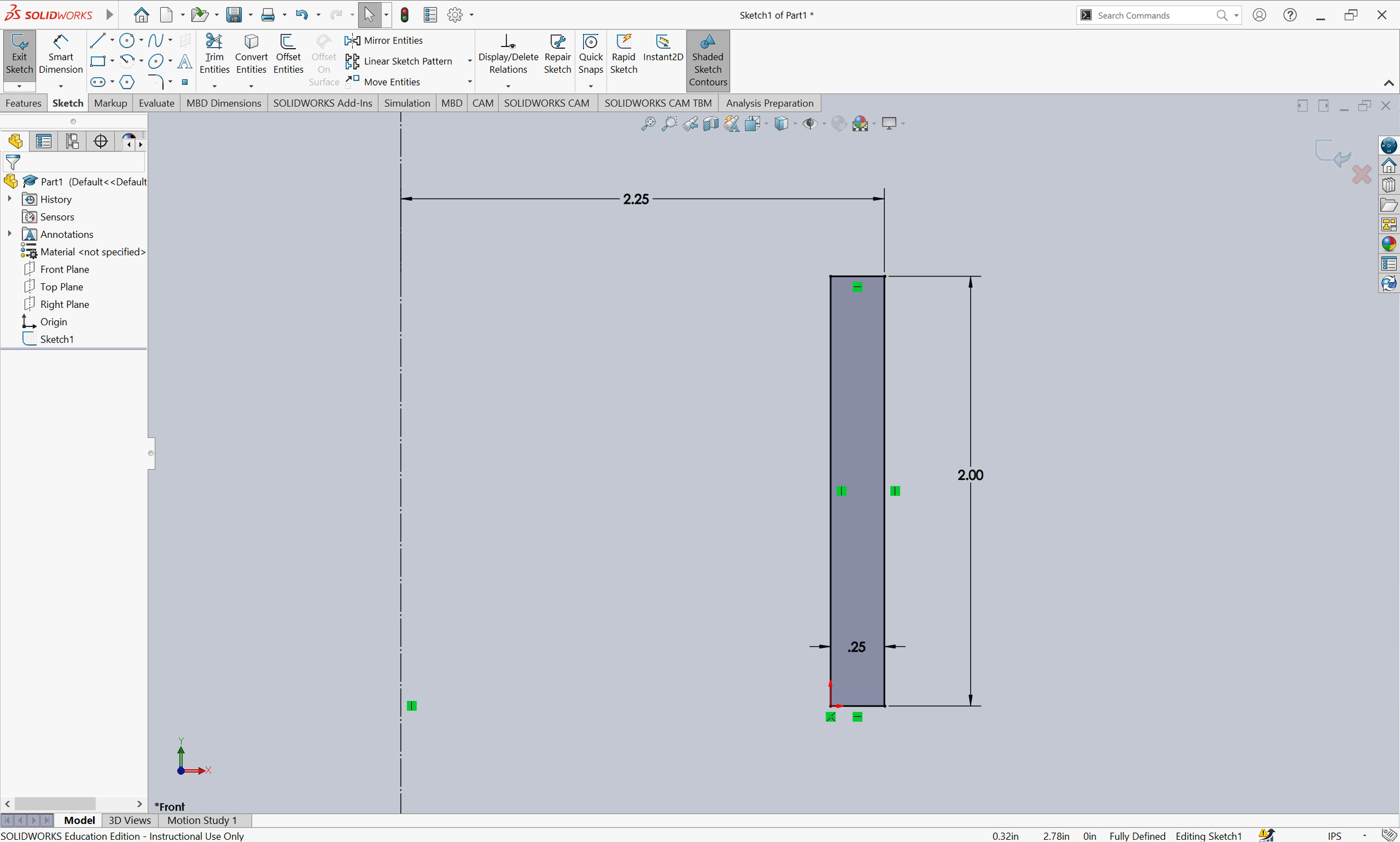
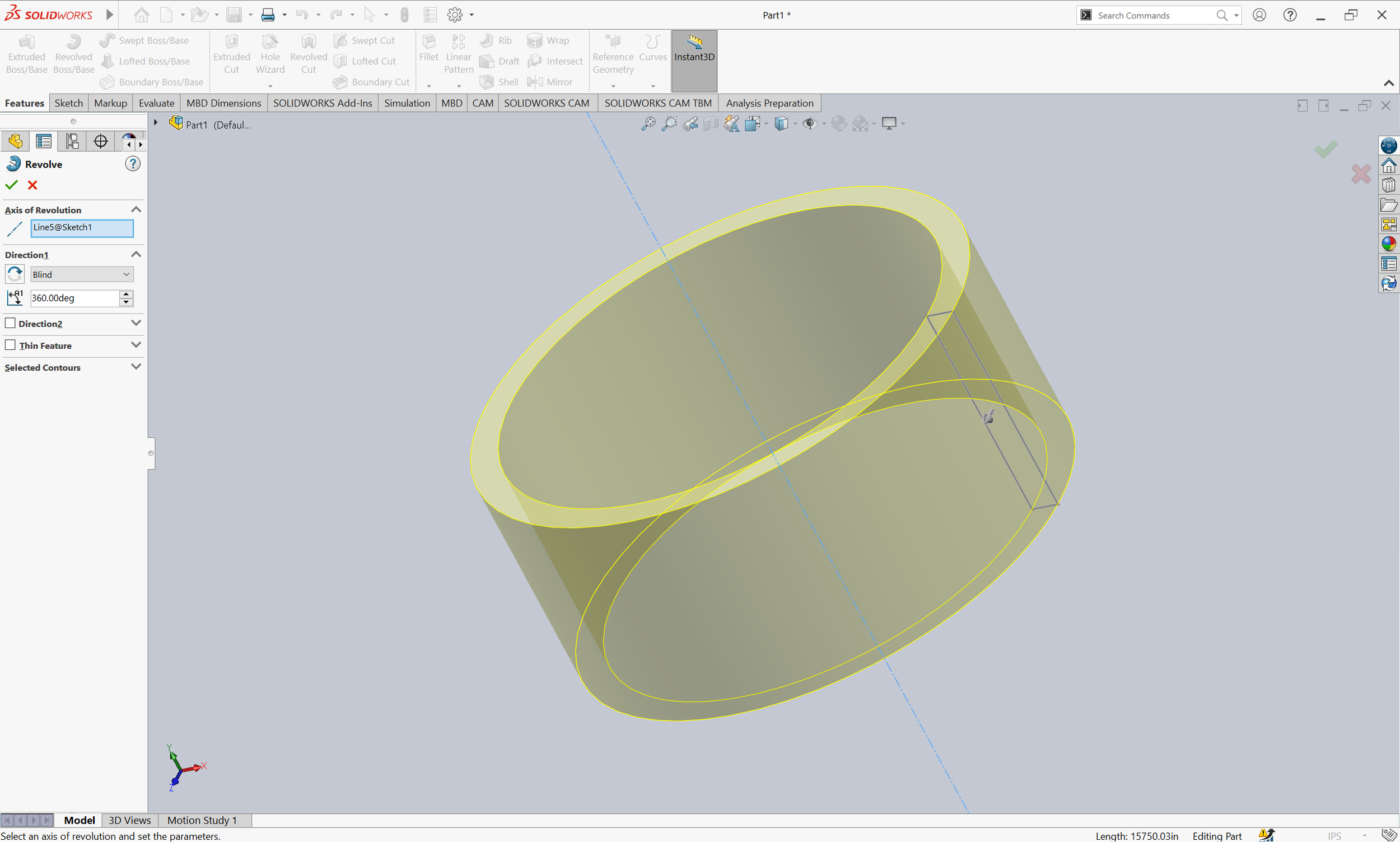
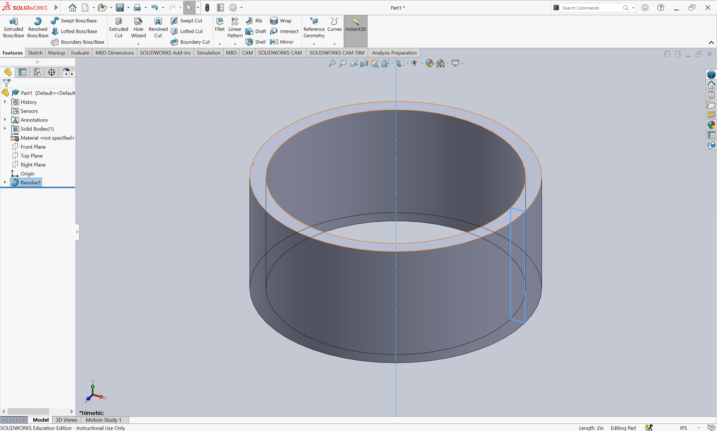
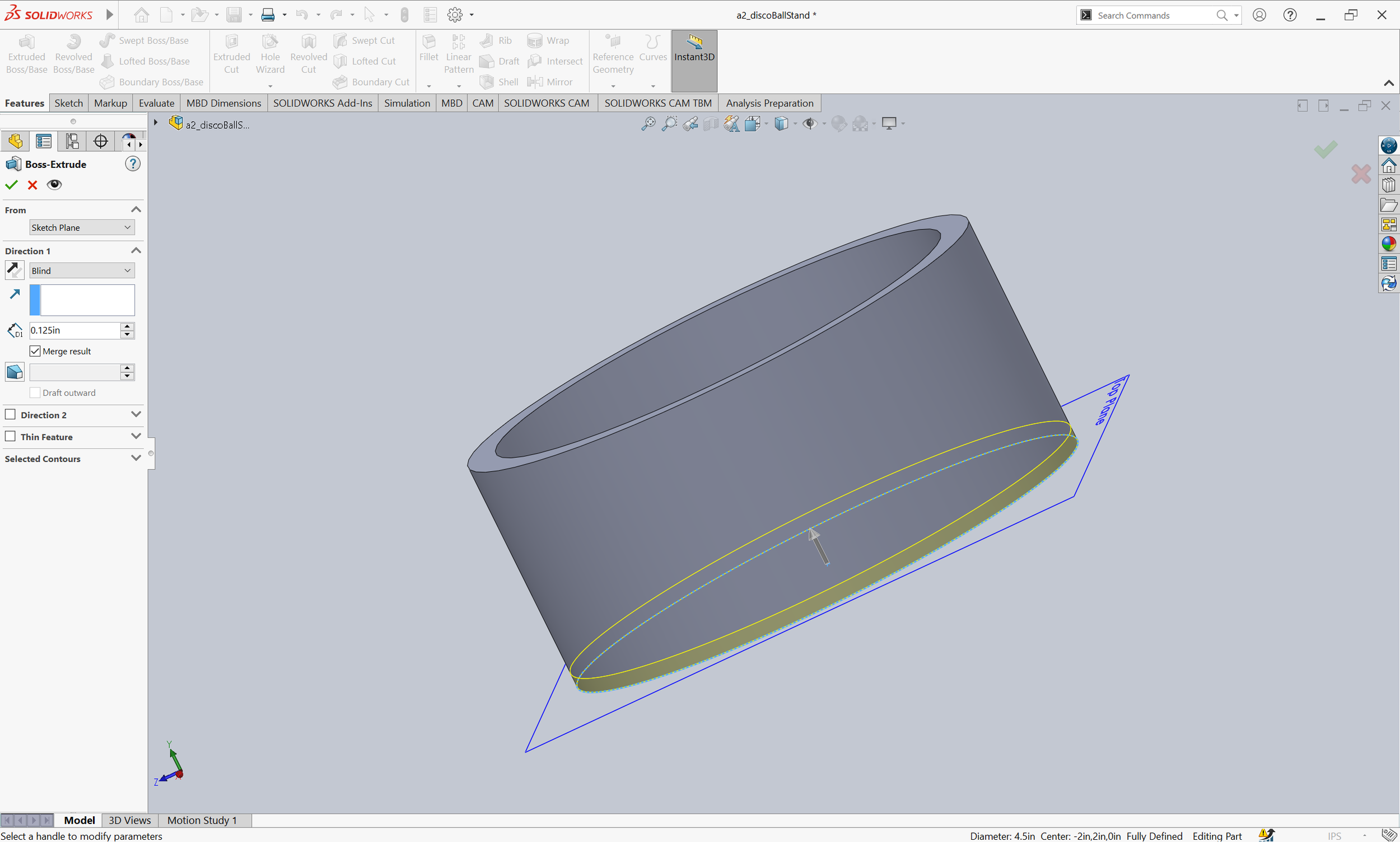
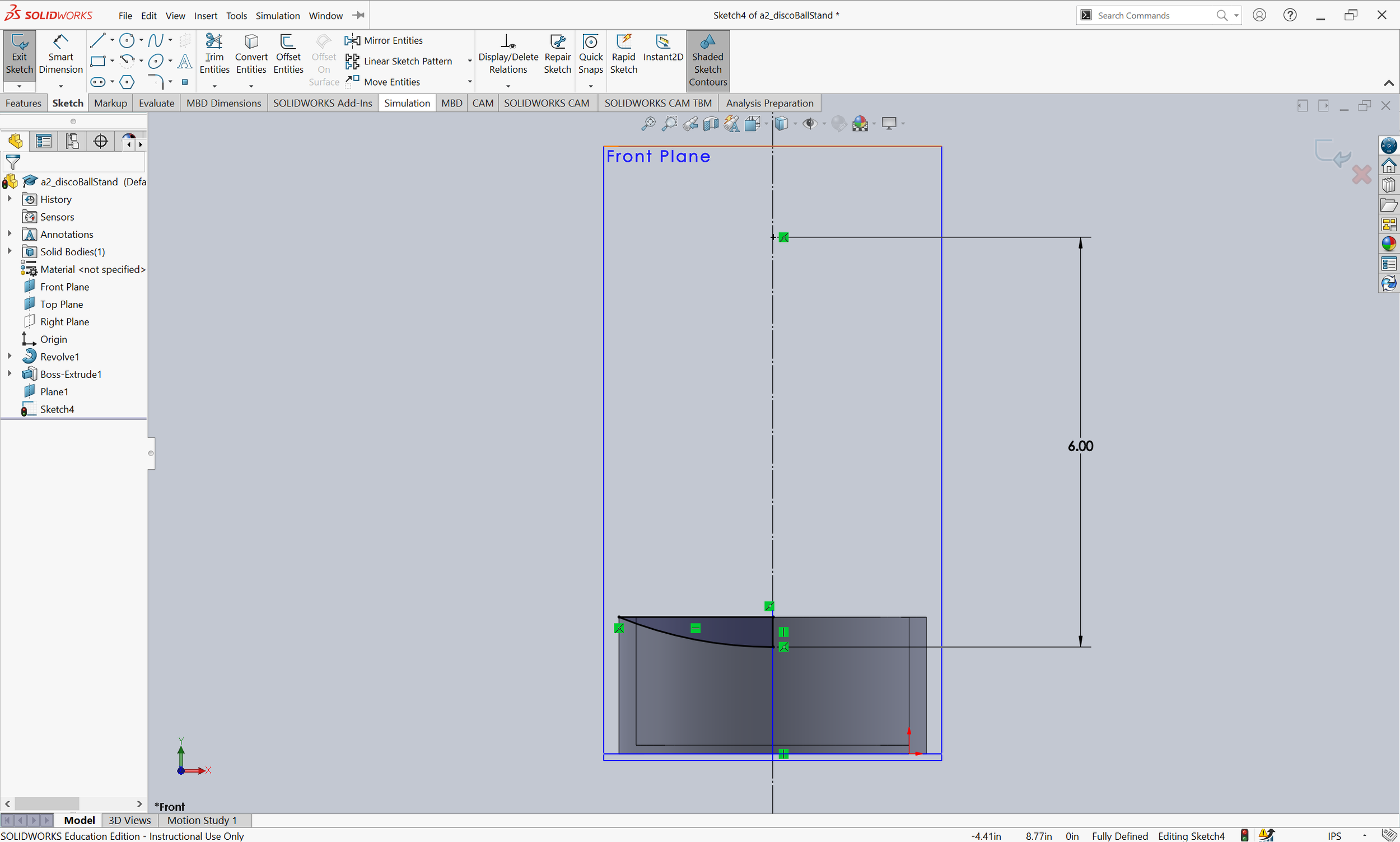
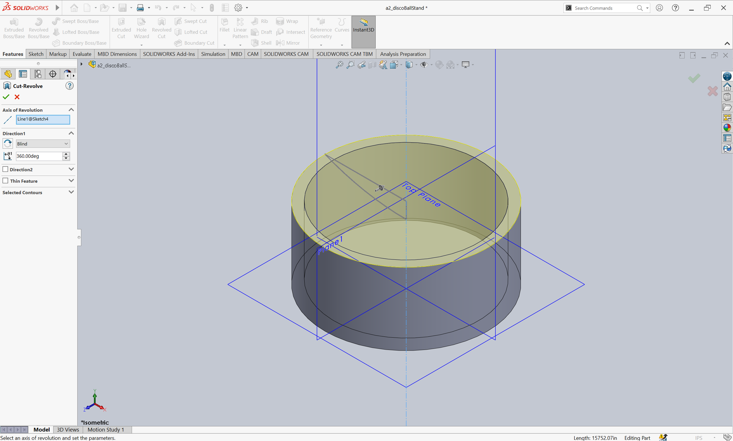
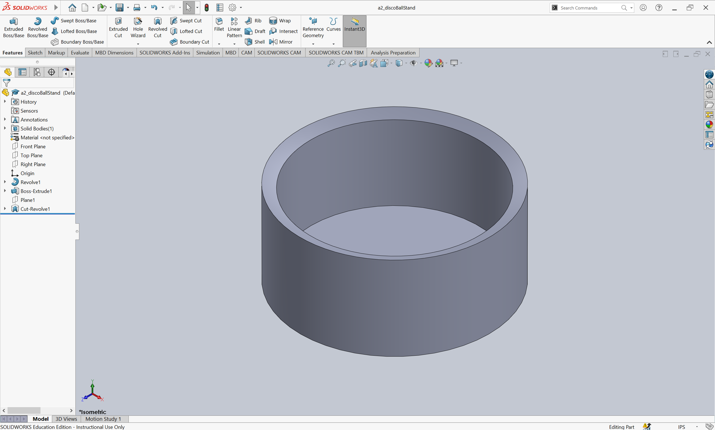
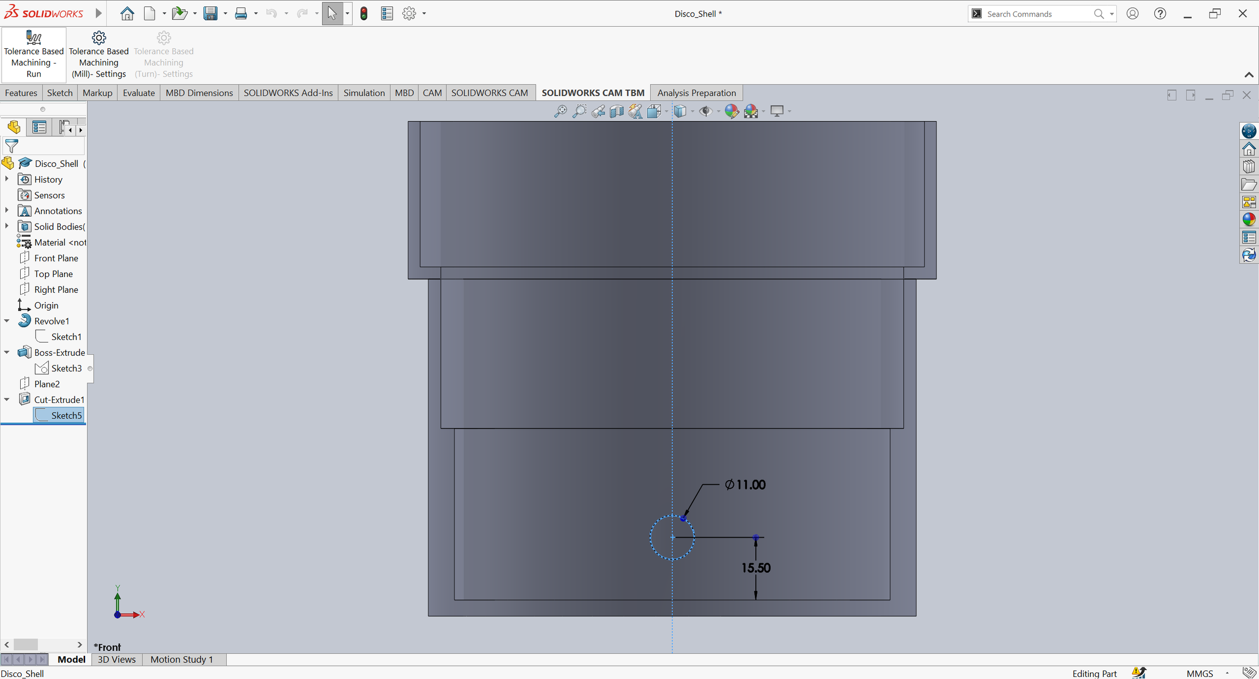
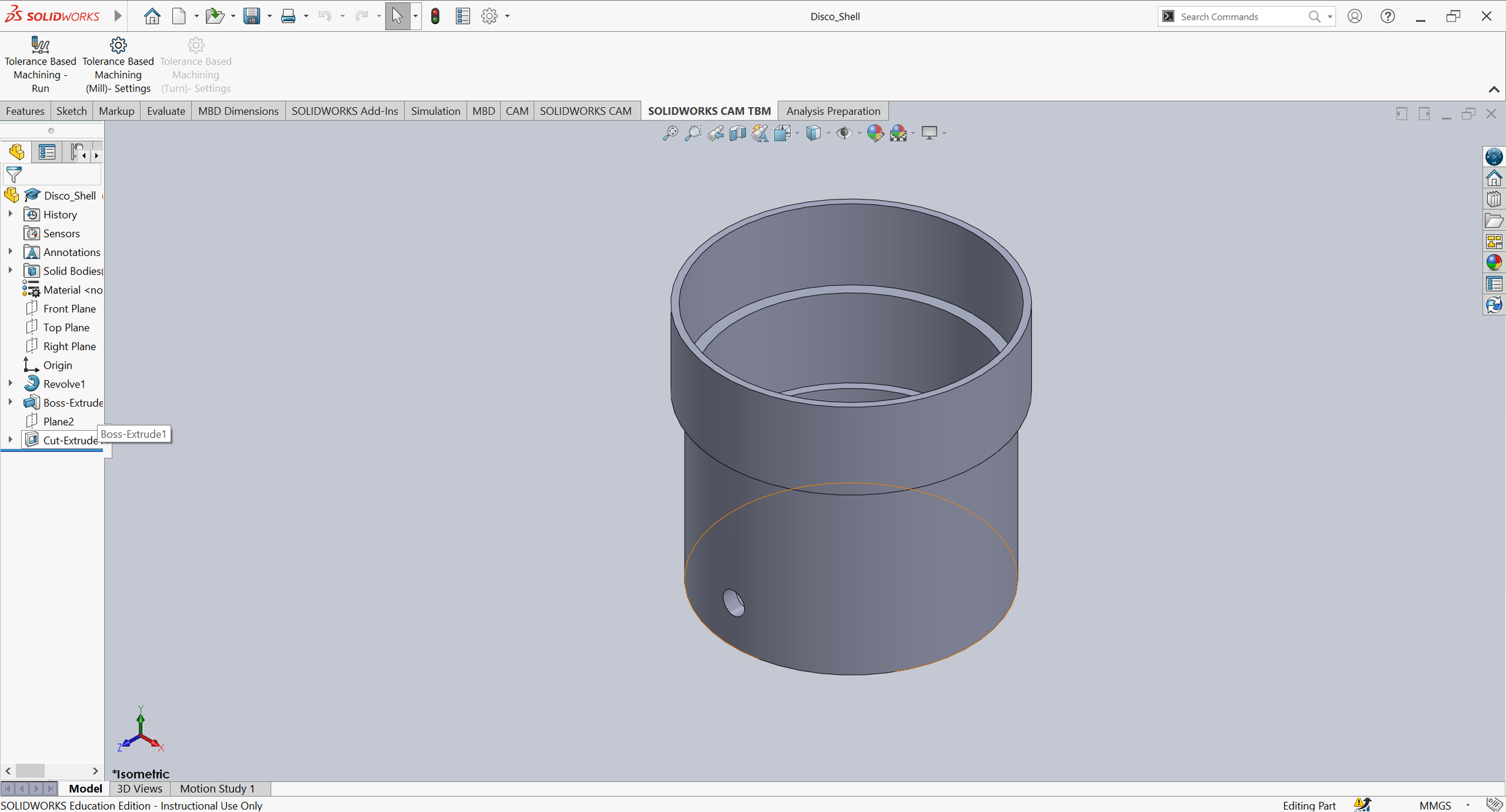
3D Modeling in SolidWorks
Prototype
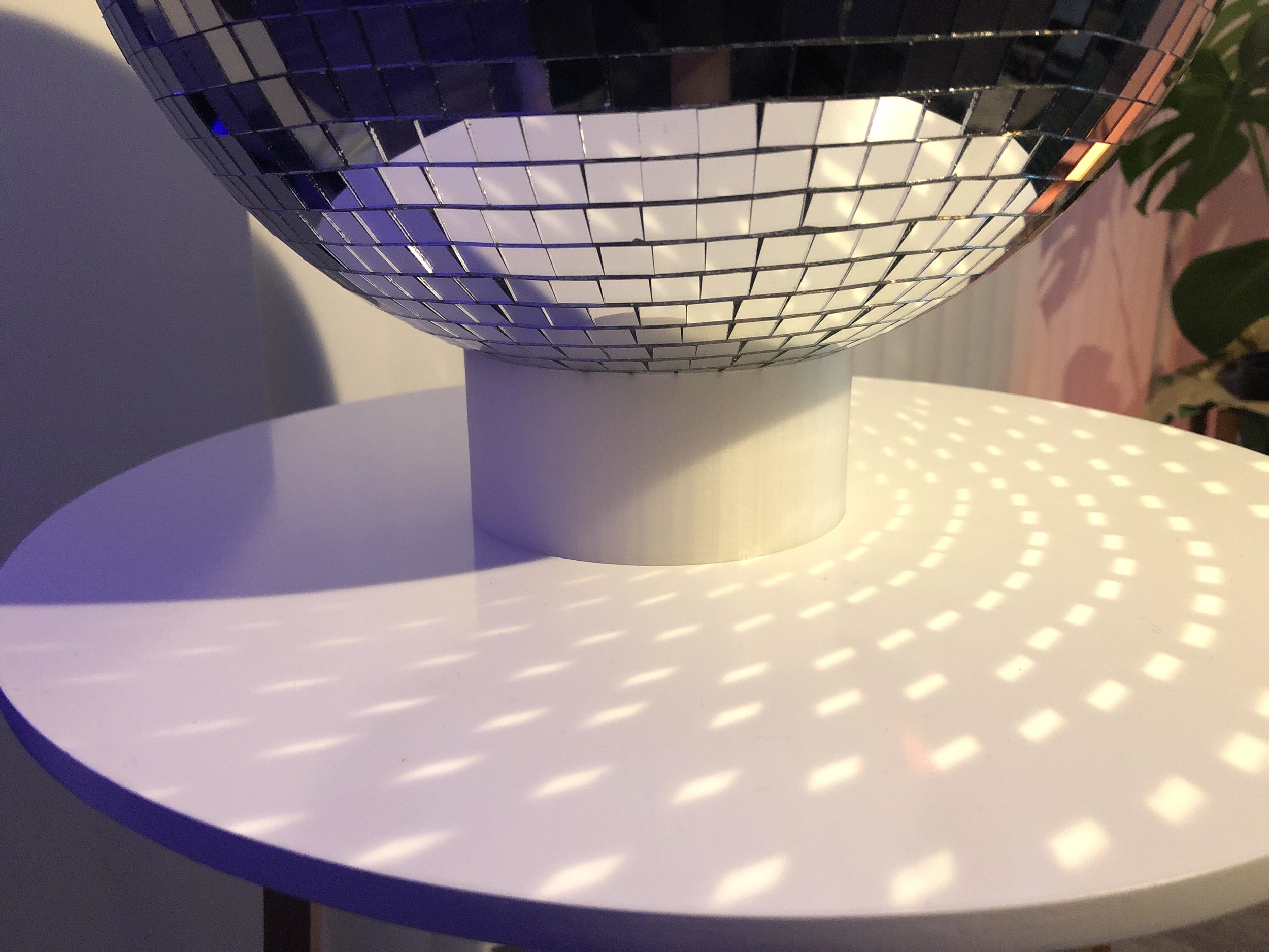
I then 3D-printed the stand (4h18min).
3D-Printed Disco Ball Stand (Printed on a Dremel 3D45)


User Testing
I conducted one user test with the 3D-printed prototype. The user was one of my neighbors in my apartment building. I tested for usability, feasibility, and desirability.
The user placed the disco ball on the stand. I observed how well the disco ball stayed on the stand, checking for sturdiness and if it was prone to fall over.
Usability
The user placed the disco ball on the stand a second time, but this time they hid the hook in the stand. I observed how long this task took to complete and looked for potential pain points.
Feasibility
I asked the user what they thought about the disco ball stand and how they would improve it to be more desirable.
Desirability
Feedback & Solutions
Observations from the user test and critique feedback from my design peers.
User Test Feedback
The bottom of the 3D model is too smooth and slides around too easily. The stand and disco ball could potentially slide off the table if pushed accidentally. I could add rubber feet to the bottom of the stand.
It would be cool if the stand could spin the disco ball. I’ll make this change for the second version.
The stand is sturdy, easy to use, and the user likes it!
Critique Feedback
My design peers echoed the same feedback from the user test. For further improvements, they suggested that I add lights to the base of the stand and consider applying both laser-cutting and 3D-printing methods. The base could be made taller to hide additional components.
Let’s do this again.
02. Smart Stand
Design
The goal is to create a 1-2 minute video that comprehensively and concisely communicates the motivation, usage, and functionality of the disco ball stand, reimagined as a smart object.
Key Design Considerations
I want the second prototype to spin. The smart aspect of the reimagined stand would be its ability to detect the disco ball and automatically begin spinning (due to time constraints, this feature was faked in the video). The key design considerations are that the stand should:
Spin the disco ball. Utilize a microcontroller and stepper motor.
Only be as tall as necessary to house all electronic components.
Hide colorful electronics.
Have a place for LED installation (due to time constraints, lights were installed after the video).
Be 3D-printed with a translucent material to diffuse the lights.
With these design considerations in mind, I began working on the first redesign of the disco ball stand.
Redesigning Twice
First Redesign Sketches
The new stand would have 3 main components: a 3D-printed bowl for spinning the disco ball, a 3D-printed shell to house the bowl and electronics, and a flexible laser-cut exterior to hide the electronics. I would use an ESP8266 microcontroller to program the stepper motor and eventually the installed lights.
My biggest concern was my stepper motor's ability to support and spin the weight of the disco ball. So I tested it. The stepper motor was able to spin the disco ball. However, I learned that the motor had to be firmly planted on a flat surface, otherwise, the weight of the disco ball would cause the motor's body to spin instead of the disco ball. I had to redesign my first idea to be more structurally sound.
Additionally, I wanted to eventually light up the stand with 5 individual RGB LEDs, but I realized that there weren’t enough pins on my microcontroller to support all 5. I needed to use an LED strip instead.
Second Redesign Sketches
For the second redesign, I made changes to the internal structure to include a ledge. This ledge would support a laser-cut disk which I would securely attach the stepper motor to. I also redesigned the bowl that holds the disco ball to be smaller around the base to allow more room for the LED strip.
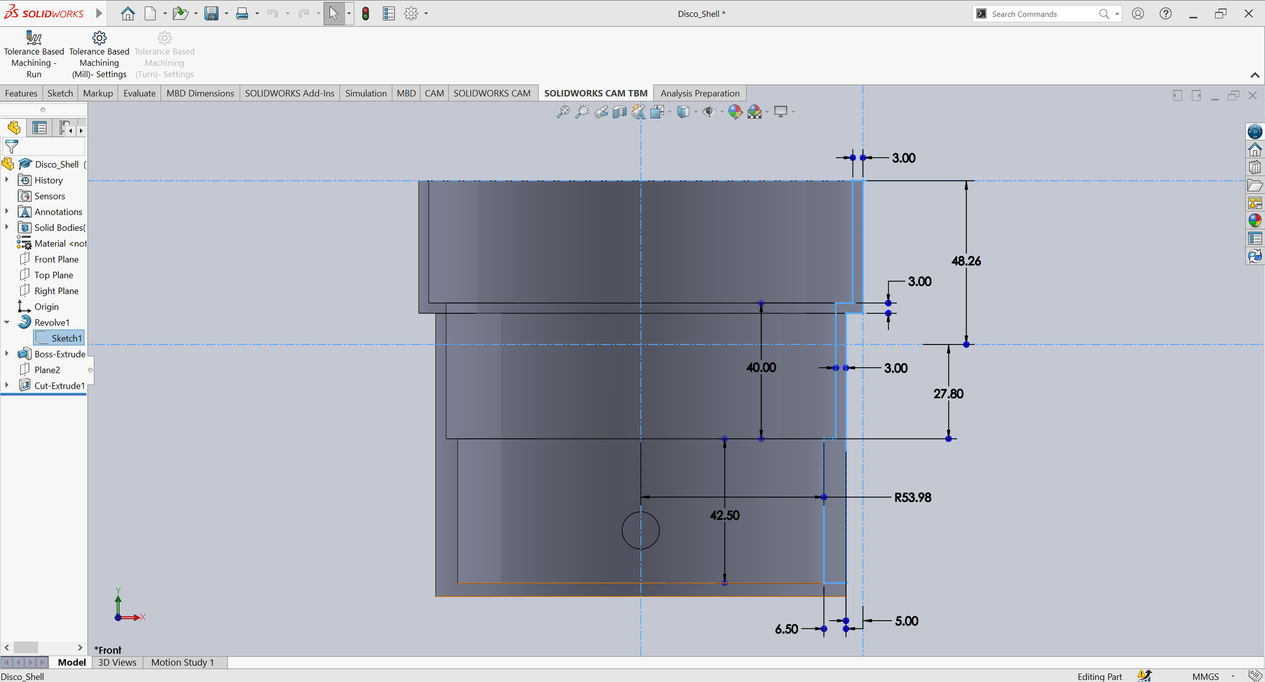
3D-Modeling in SolidWorks
I modeled the shell and bowl in SolidWorks. The main operations used were extrude, extrude cut, revolution, and fillet.
3D Printing
The shell was a 10hr54min print and the bowl was a 4hr39min print. Both prints were done in a Dremel 3D45.
Laser Cutting
I laser cut the exterior piece of 5mm thick plywood that wrapped around the shell, a disk to mount the bowl on, and a disk to mount the motor onto. I used a wave lattice kerf pattern to laser cut the exterior wood to be flexible.
Laser cutting in progress.
Two kerf patterns I experimented with.
Realizing my first attempt at the exterior piece was too short, and I forgot to cut out the hole for power.
Programming the ESP8266
Programming was simple. I powered the board and the motor with a 5V wall power supply.
Assembly
Once all components were completed, I started the final assembly. I inserted all electronics, attached the motor and bowl to their respective laser-cut disks, and superglued the exterior wood piece to the outside of the shell. The disco ball stand was done, and I was ready to start the video process.
Video
My goal for the video was to showcase the product. Prior to any filming, I began by making shot lists and taking notes on how to edit the footage. I filmed and then edited the video with Adobe Premiere Pro.
Sketches of different shots I wanted to film.
More sketches.
Critique & Analysis
I presented my video (prior to adding sound) on critique day (11/09/2021) to my HCDE 451 UX Prototyping class and received feedback from my instructors and 7 of my classmates.
Feedback & Potential Improvements
Show vs. tell by including more shots of yourself having difficulty hanging the disco ball up. The introductory text messaging exchange could overlay a shot of me attempting to hang the ball up.
Bring the text messaging back around at the end for a more complete resolution. There could be a brief two-message exchange between the two texters at the end, where one shares an image of the final stand and the other reacts.
Add audio to the video to make it more exciting. I made this change!
The introductory text message exchange was a creative and concise way to set the scene and introduce the problem/need.
The shots look well done, and the video is clear. There was no confusion.
The redesign of the disco ball stand is successful.
Reflection
What I Would Do Differently in the Future
I wish that I had taken more photos throughout the process. I forgot to take photos of the 3D-printed and laser-cut components prior to assembly.
Allocate more time towards video planning, filming, and editing in the future! Although I did plan, I ended up scrapping a large portion of my video plan, since it didn't look like what I had imagined when being executed. Make time to experiment with different shots!
Key Findings & Learnings
Test the design throughout the process! If I had not tested my stepper motor's ability to spin the disco ball or my first redesign of the stand during the process, I would have wasted a lot of time printing a structure that wouldn't have been supportive enough. Quick tests help inform the design, reduce anxieties about whether something will work, and save time overall.
This entire process was a lot of trial and error. I spent around 32 hours on the second prototype total, including 3D-modeling, programming the microcontroller, making shot lists, filming, and editing. 24 of those 32 hours were spent physically at the Mill (a makerspace at the University of Washington) working on the design, 3D-printing, laser-cutting, and assembly of the disco ball stand. I was able to make mistakes, learn from them, modify my designs, and make multiple versions of different components.
Want to create the Disco Ball Stand?
All files can be found on my GitHub! Select a version of the Disco Ball Stand below to access those files.
ON THE PLAYGROUND: MINI TABLETOP BOWLING GAME | SHOE RACK & SHOE STACKERS | KIRBY | APPLYING UX TO MY LIFE

